- Объём
- 181 страница
- Формат
- PDF · 5 МБ
- Раздел
- Инструкции
Скачать бесплатнонужна регистрация — минута через VK ID или Яндекс ID
Загляните внутрь — первые страницы
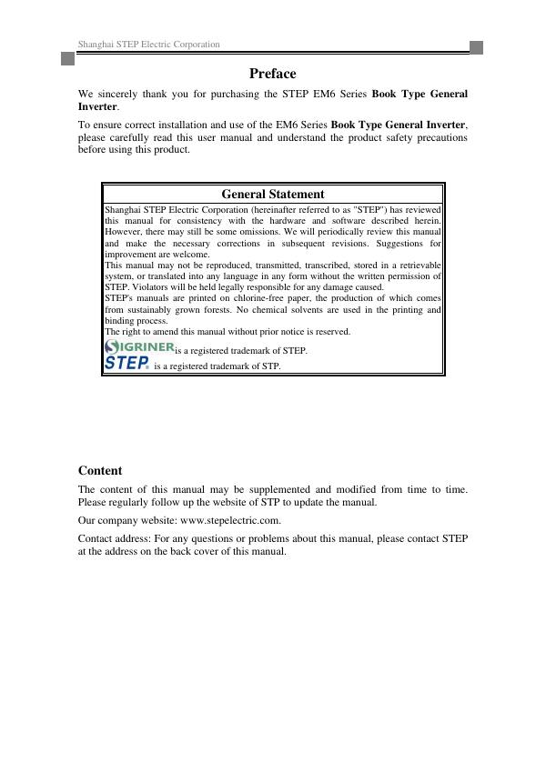
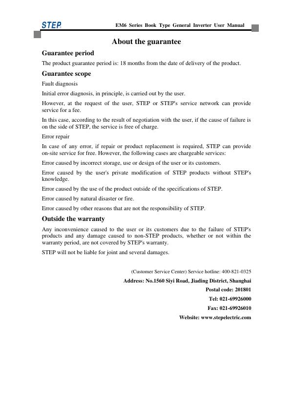
Дальше — в файле (181 стр.). Скачать целиком бесплатно
Официальная документация: Документация и ПО / STEP. Поставка и техническая поддержка в России — АРТ Технолоджи (art-t.pro).
Оглавление
- Chapter 1 Safety Instructions11
- 1.1 Description of safety-related markings11
- 1.2 Safety matters12
- 1.3 Precautions16
- Chapter 2 Product Overview19
- 2.1 Description of the nameplate and specifications19
- 2.2 Technical performance and specifications of the inverter21
- 2.3 Installation dimensions of the inverter22
- 2.4 Option of braking resistor26
- Chapter 3 Installation of the inverter28
- 3.1 Installation steps28
- 3.2 Mechanical installation28
- Chapter 4 Wiring of the inverter32
- 4.1 Connection between the inverter and peripheral equipment33
- 4.2 Inverter terminal wiring37
- 4.3 Wiring of main circuit terminals38
- 4.4 Anti-interference measures41
- 4.5 Wiring of control circuit terminals43
- Chapter 5 Commissioning and trial operation49
- 5.1 Running command setting49
- 5.2 Standard configuration LED operator introduction50
- 5.3 LED operator commissioning process51
- 5.4 Optional configuration LCD operator introduction52
- 5.5 Operation of LCD operator52
- 5.6 Fault display56
- Chapter 6 Function parameter table57
- 6.1 Description on function code parameter table57
- 6.2 Brief table of function code parameters57
- Chapter 7 Explanation of parameters77
- 7.1 Parameter group classification and format77
- 7.2 Group P0X User parameters group78
- 7.3 Group P1X Control parameter group78
- 7.4 Group P2X Motor parameters92
- 7.5 P3X group Terminal function97
- 7.6 P4X Group Velocity Parameter Group110
- 7.7 P5X group Process control114
- 7.8 P6X group vector control120
- 7.9 P7X group Enhanced control122
- 7.10 P8X group Communication control129
- 7.11 P9X Group Fault and Display Parameter Group131
- Chapter 8 Fault checking137
- 8.1 Protection and inspection functions137
- 8.2 Fault diagnosis process141
- Chapter 9 Care and Maintenance143
- 9.1 Warranty period143
- 9.2 Product inquiry143
- 9.3 Routine inspection143
- 9.4 Periodic inspection144
- Appendix A EMC Installation Guide for the Inverter147
- A.1 Noise suppression147
- A.2 Distribution requirements149
- A.3 Grounding150
- A.4 Installation of surge absorber151
- A.5 Leakage current and its countermeasures151
- A.6 Radiation emission suppression of the inverter152
- A.7 Guide to the use of power line filter153
- A.8 Division of EMC installation area of the inverter153
- A.9 Precautions for electrical installation of the inverter155
- A.10 EMC standards met by the book type general inverter156
- Appendix B Standards Suitable for the Inverter157
- Appendix C Modbus Communication Protocol159
- C.1 Command data [Register 3, 6] [Bit 1, 5]159
- C.2 Monitoring data [Register 4] [Bit 2]161
- Appendix D Profinet Communication Description167
- D.1 Introduction to Network Settings167
- D.2 Protocol Content168
- D.3 Protocol Usage175
- Customer complaint177
- Warranty Card178
- Warranty Agreement179
- Customer Notification180
Файлы
Скачивание доступно зарегистрированным участникам сообщества. Войти или зарегистрироваться Вход через VK ID или Яндекс ID занимает минуту.